On this page you can find all about the construction of the CanSat.
Schematic overview
 |
| Click on the element to show details |
The mounting system
The modules can be fixed on our mounting system consisting of four threaded rods (3mm) by nuts.
To fix the board of the Pi on our mounting system we used the existing holes on the Pi. We made a connector of a wood-like material.
This has appropriate holes for the Pi and for the mounting system. This connectors also fix the batteries.
 |
| connector without batterie |
|
 |
| connector with batterie |
|
In order to control and reduce the staggering of our CanSat during the drop, we tried to distribute its weights symmetrically. Additonally we we place the additional weight about this module, because this should stabilize the fall together with the recovery system, too.
The camera/sensor modul
This modul contains the most important sensor: The camera. We are using the PiCam V2. Furthermore we fixed on this board the BMP280 (barometric pressure, temperature, altitude sensor) and the main power switch, too.
 |
| Front view: the sensitiv site of the sensors |
|
 |
| Back view: the contactable site of the sensors |
|
The additional weight
The guidelines require the CanSat to weigh between 300 and 350 grams.
Because our CanSat only weighs 220 grams we needed to add at least additional 80 grams of extra weight.
We
choose to use lead as extra weight again because of its high density
and softness, but this time, instead of strapping strips of lead to the
batteries with cable ties we choose to melt the lead in the same form
our circuit boards are (see pictures in gallery).
By doing so we are able to simply bolt the lead plate onto our CanSat like our circuit boards.
The
plate will be fixed to the bottom part of our CanSat in order to help
stabilize the fall so our CanSat can take some steadier pictures.
|
 |
| first version of the lead plate |
|
 |
| installed additional weight |
|
 |
| second version (and now installed version) |
|
Each plate (we made two of them for our two CanSats) weighs around 90 grams, which would make our CanSat weigh about 310 grams.
The Raspberry Pi 3
 |
| modified Pi 3 without some connectors that we don't need |
We are using a Raspberry Pi 3, because it clearly provides us more
RAM than the Pi 2B. Besides, we urgently need this computing power for
our mission. The Raspberry Pi 3 is a board computer and is the working
brain of our CanSat. It will do the optical position determination for
us. It also manages the saving and sending of collected data.
Our sensors are supplied and powered by the GPIOs. We made room by removing the ethernet and A/V ports. This gave room for the charging electronics.
 |
| Due to this modification, we have access to the USB interface without having to disassemble the satellite every time. |
The power supply
 |
| Li-ion cells connected in parallel |
|
 |
| charging electronics (packaged in a black shrink tube) |
|
 |
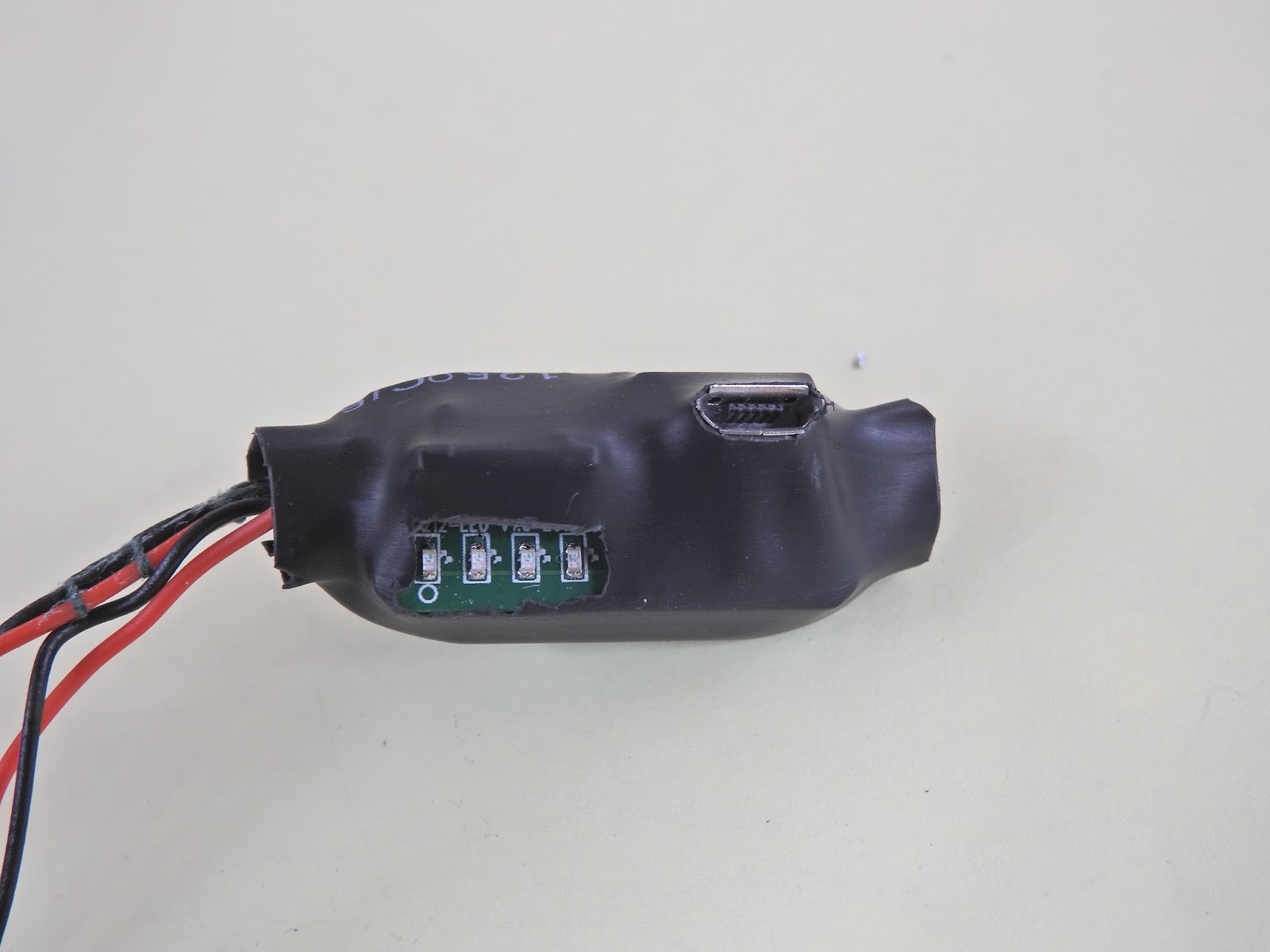
| 4 blinking LEDS of the charging electronics. |
|
We are using two LGABF1L1865 Li-ion cells which we salvaged out of a USB powerbank. Each of those cells can hold 3350 mAh and because we connected them in parallel we get 6700 mAh in total.
Should our CanSat draw 1 A @ 5 V we could expect our batteries, if fully charged, to power our CanSat for a total runtime of around 6 hours and 42 minutes. The charging electronics (packaged in a black shrink tube and fixed on the board of the Pi) give us the current charge level via 4 LEDs.
 |
| here the charging electronics fixed on the Pi (site view) |
|
 |
| here the charging electronics fixed on the Pi (bottom view) |
|
|
 |
| here the attachment of the batteries |
The orientation module
This module contains everything we need in order to determine the position of our CanSat. We have integrated two sensors in this module: The first one is a GPS receiver and the second one is an orientation sensor.
The GPS receiver will help us with finding our CanSat after the landing. Furthermore, the gathered position data of this GPS receiver will serve as reference data to our optical position determination. It will also give us the system time and the altitude.
Added to that we have a controll LED fixed on this board, which can be programmed for anything.
 |
| front view |
|
 |
| back view |
|
The orientation sensor contains of an acceleration sensor, a magnetometer and a gyroscope. The sensor can be operated in various individual modes, and when it is requested, it will safely supply the data from the sensors.
It also includes “fusion modes " for relative orientation (IMU) and an absolute orientation (compass). In the IMU, only the date of the acceleration sensor and the gyroscope are to be collected, therefore the acceleration sensor and the magnetometer are used in the compass.
Because of this flexible concept, we have chosen this sensor, and therewith we will be able to determine the orientation of our CanSat.
These information are important for us, so that we can form an animation of the drop of our CanSat and be able to judge, from which angle our pictures have been taken.
 |
| the intelligent 9-axis absolute orientation sensor |


No comments:
Post a Comment
Note: only a member of this blog may post a comment.